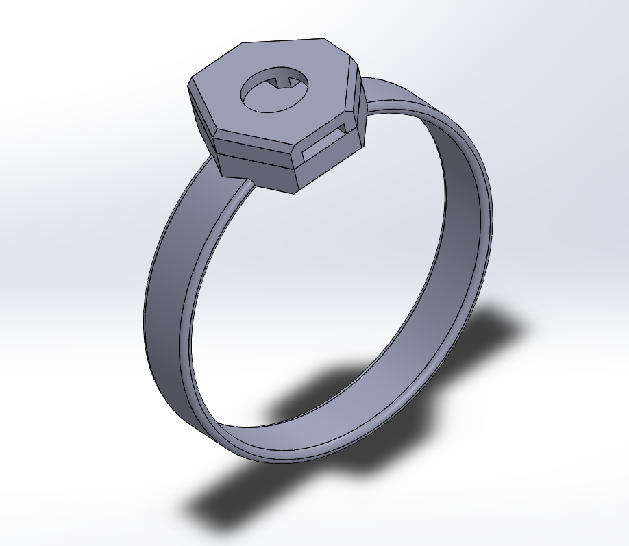
The prototype was modeled and in the form of a ring. The ring was divided into two parts and a neodymium magnet would be placed both in the upper part and the floor part so that the devices can be exchanged easily. The width of each ring ranges between 10mm to 15mm so that it can bear the trackpoint with a diameter of 8mm. Three circumferences of the rings were chosen from the statistical anthropometric data.
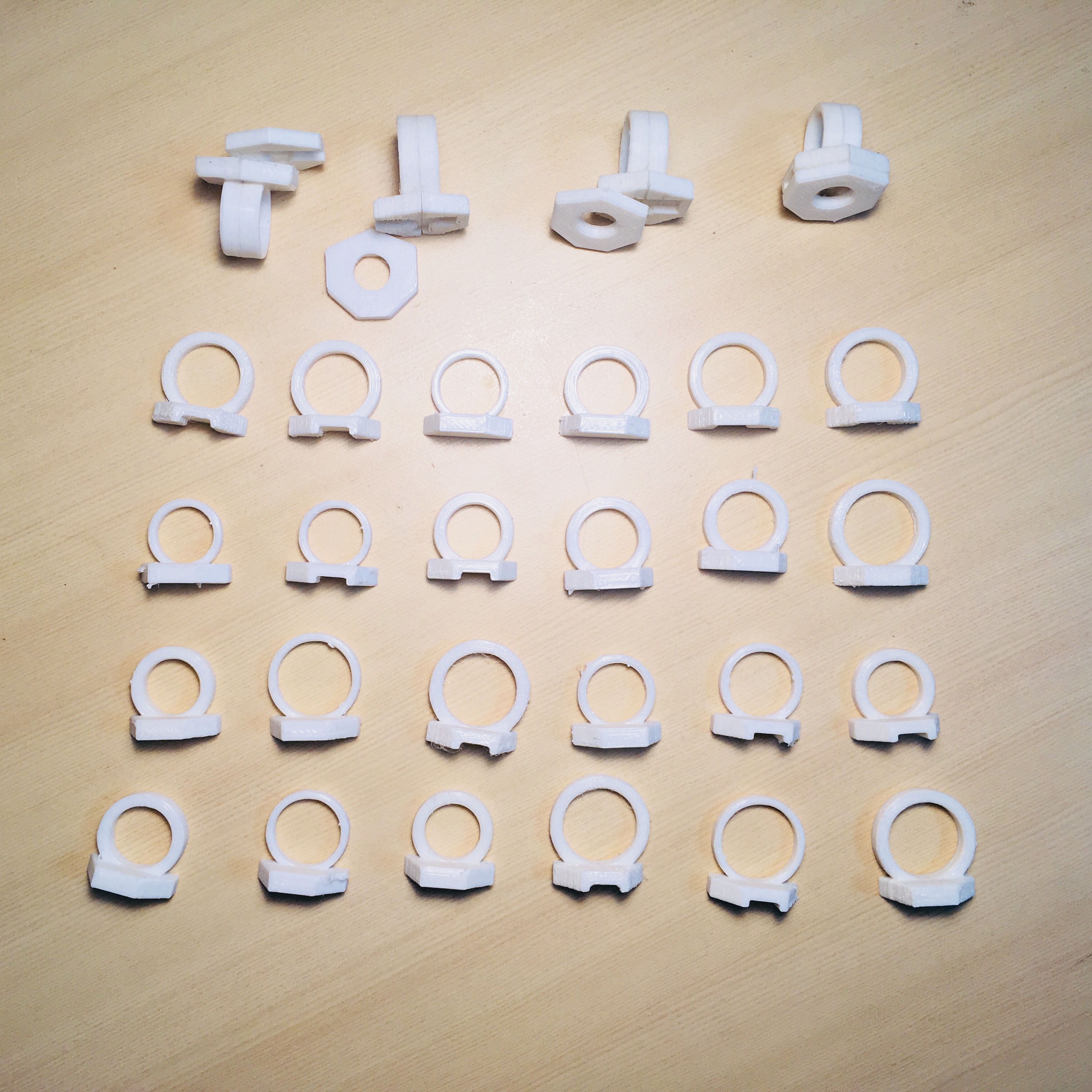
modeling process
</br>
A render shot of the prototype
</br>
We tried 12 variations of ring prototypes in terms of 3 circumstances(5th percentile, 50th percentile, 95th percentile), 2 widths, 2 thicknesses based on anthropometric data
Fitts’ Law
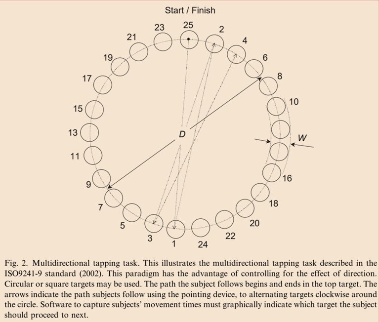
We reviewed a paper called “Towards a standard for pointing device
evaluation, perspectives on 27 years of
Fitts’ law research in HCI” to refer on evaluation of our devices.
In one experiment, multiple ID values should be shown. Each condition should be shown from 15 to 25 times.
Movement Time (MT) needs to be measured, while the time used to move the pointing device (homing time, dwell time and etc.) should be eliminated.
Scatter of subject’s movement end-points should be gathered by either determining the error rate or recording the physical end-points. This is to ensure that no data is filtered and conduct accuracy of adjustment.
Throughput: overall measure of performance. In addition, Movement Time(means for each ID condition), error rates(per condition), end-point variation(standard deviation of end-point position per condition)
Conclusion: Error rate -> effective width -> effective index of difficulty -> movement Time -> Throughput
Mentor meeting
We asked our mentor TAs some questions about the paper and our experimental plan.
How to measure end-point scatter data?
Set the standard as distance between target and user’s selection. If the input system is good, the precision/accuracy should be high so the standard deviation will be low. On the other hand, error rates could be calculated only using success and failure.
Specific experimental design?
About three target sizes and a couple of distance types could be used. One set of experiment could be divided into a number of blocks so that participants can be given break time.
7 subjects per device would be enough, even when considering an outlier.
No need to consider gender problems (but try to match the ratio) but think about eyesight problems (glasses)
If the trial fails, it should be done again; the subject should be informed in advance that they should do their best in order to lessen time
Things to be measured on HoloLens?
error rate: (number of failures) / (number of total trials)
The distance between the center of each target and the end-point
Week 12 - Unity
Unity application
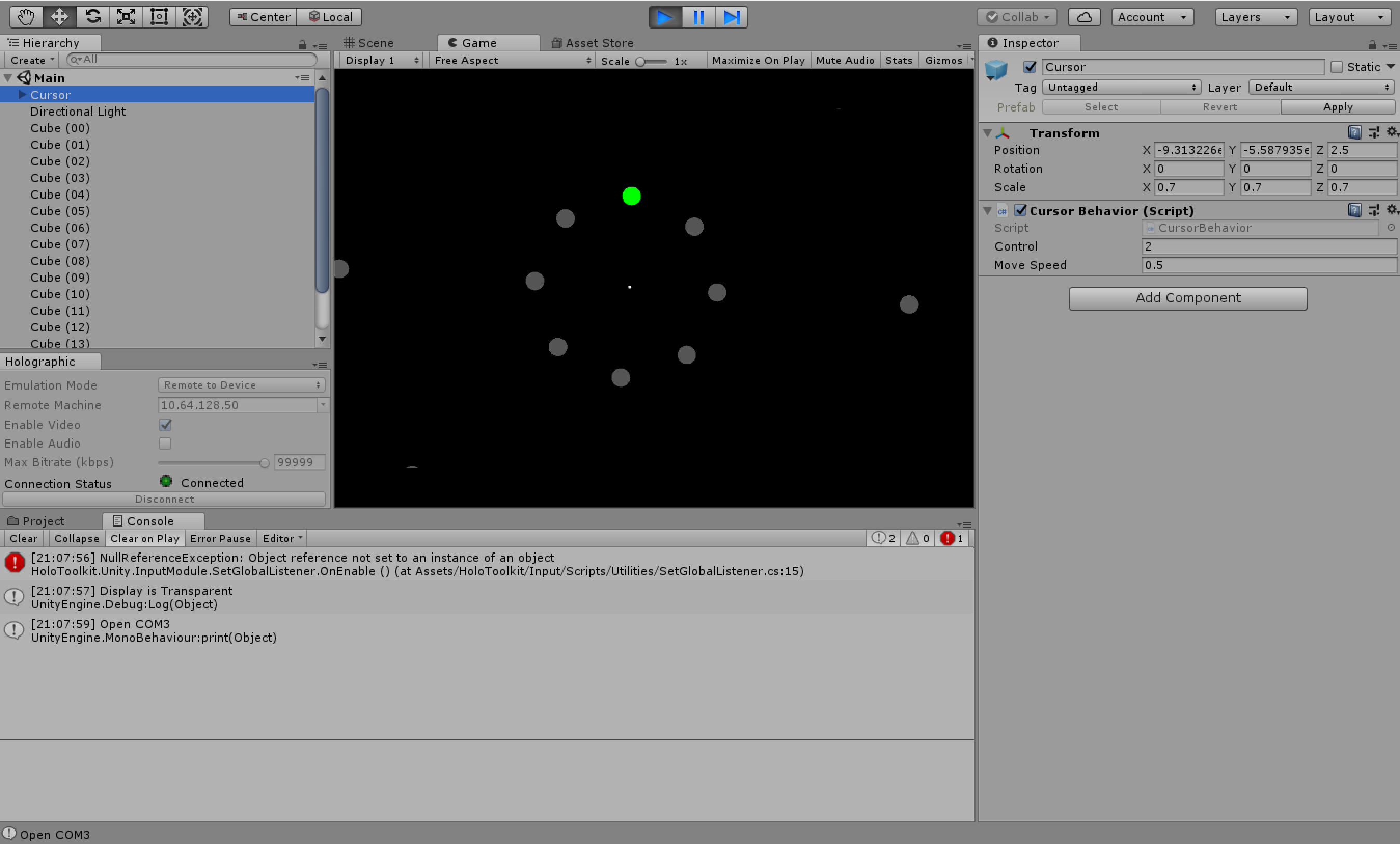
We made an unity application for experiment.
If a cursor is above the target (gray circle), then it changes its shape from circle to doughnut.
The target that the user has to click is green, clicked target is blue and the others are gray.
The position of each targets is reffered to this paper.
8 targets are positioned in 45 degrees apart from each other.
Near is 7 degrees and far is 21 degrees from eye position.
Cursor is controlled by a trackpoint that connected with bluetooth.
Unity applicationDemonstration on HoloLens
Week 11 - Interim Presentation
Previous works
There were three main problems in HoloLens interaction: gaze, pointing gesture, and voice input. We were to come up with a finger augmented device that will integrate the solutions for each problem - specifically, we wanted to create a ring with a trackpoint.
Specified goal
Within finger augmentation, we discovered that most of the current input devices rely on movement only, such as the joystick or the mouse. On the other side, we found out there are some devices that are based on pressure, which are less common and therefore have more value in research than movement-based ones. We also saw the advantage of the pressure-based device as having no push-backs when using, and the potential to be utilized in many different ways.
Moreover, the previous research question had some issues regarding the similarity. we wanted to compare the head gaze and our device and see how they would each work in conducting the original tasks in HoloLens, but we realized that our targets of comparison were too different from each other, which means there would be more independent variables to consider. Therefore, instead of simply creating a new device, we decided to develop and compare two finger augmented input devices, the pressure-based one and the movement-based one. In particular, we will compare the isometric trackpoint to the isotonic trackball using movement and selection tasks.
Prototyping
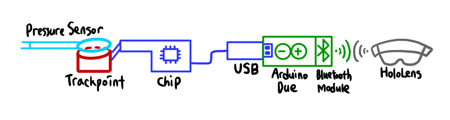
We bought a thinkPad keyboard from Lenovo and and successfully disassembled the trackpoint from the keyboard. However, the problem was that the trackpoint cannot select but can only move the cursor. Therefore, we will implement a pressure sensor on top to recognize ‘click’s.
Then, we connected the trackpoint to Arduino DUE using microUSB input. On the Arduino, a Bluetooth module was connected as well since HoloLens only recognizes external devices through Bluetooth signals.
The trackball, on the other hand, will be connected to Arduino UNO because it originally is a part for Arduinos. And this will need a Bluetooth module for the same reason as trackpoint.
In addition, about the ring shape - Considering the comfort, our ring prototypes will be made through 3d Prining using some elastic filaments such as NinjaFlex or SemiFlex.
Evaluation
At first, we thought of using Fitts’ Law: representative model of evaluating selection, but we actually cannot use it because the trackpoint itself doesn’t move. Even if we cannot apply the law to our experiment, however, we will just use the paradigm or the factors of experimental design such as time and distance between each target.
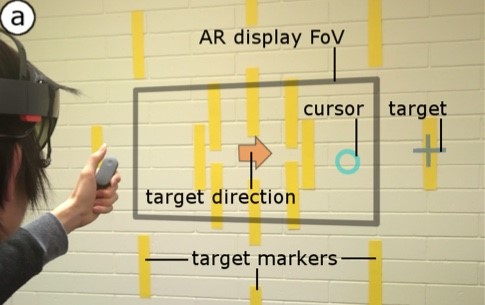
We also referred to a paper on target selection for augmented reality. The researchers used a point target selection task to measure its performance, and There were two types of targets: those near and inside the device Field of View, and far and outside the device Field of View. For each type, a total of 8 targets exist and they are positioned in 45 degrees apart from each other.
Our tasks will resemble those of the paper. There are two types of tasks. In task A, the targets will be inside the field of view and for task b, the targets will be outside the field of view. We will measure factors such as the time consumed to select each objects, the error rate, the workload, social acceptance and user’s perceived difficulties. On the other hand, the control variables should remain the same – this will include the size of target objects, the distance between two targets, and the selecting order will be the same within each task.
To-do list for next week
Finish building Unity app for experiment on HoloLens
Connect hardware(physical prototype) to HoloLens
Conduct experiments(evaluation)
Week 10 - Continue developing
Connecting a trackpoint to HoloLens
We shared our idea about the ways to connect HoloLens and a trackpoint. Professor said the first one is better because it can be applied to a trackball as the same way and it is the simplest one to make. Also, he said the last one, making an unity application can access HoloLens and a trackpoint separately, is not a good idea. He recommended developing hardware and software independently.
The reason why a trackball is also recommended
To do comparative study, features except for the part to be compared should be almost the same. In this regard, trackpoint and trackball are sufficiently similar to compare force and movement.
Usability -> Evaluation
Usability is measured in application stage. In case of out project, an input device, we have to evaluate it.
Modified Fitts’ law
Fitts’ law does not apply to a trackpoint directly because users do not need to move their finger when they are using it. So, we have to modify Fitts’ law.
To-do list for next week
Connect trackpoint and trackball to HoloLens
Develop experiment application
Week 9 - Try to use a TRACKPOINT
Roles
We decided who does what in this project.
Minseop Kim: Connecting HoloLens and Arduino with bluetooth module.
Doyeon Kim: Connecting trackpoint and trackball to Arduino.
Heena Kwag: Develop HoloLens application by Unity for experiment.
It was divided into two experiments depending on the position of the targets.
All targets are in the field of view.
All targets are out of the field of view.
In the second experiment, the experimenters need to move their head unlike the first experiment.
First Experiment Design
Advice from the professor
The professor looked through our first experimental design and gave advice on it.
Make it more specific
He said that we have to make our experiment more detail. For example, we have to decide the size of element, the distance between two elements, the order to click, and so on.
3D Fitts’ law
Most papers on Fitts’ law apply to 2D environments, so we should search papers on 3D Fitts’ law or Fitts’ law applying to AR environments.
Comparison
At first, we were going to compare our new input device to HoloLens’ gesture system. However, the professor insisted that they are too different to compare each other in the way they work. In addition, HoloLens gesture system has two behaviors (move and tap) and tap is too slow rather than move.
He suggested alternative ways.
Use ‘dwell on’ click method.
→ Click is time-consuming behavior, so remove it from two systems and compare them. Actually, ‘dwell on click’ is not a good method to apply real-life situation but there is no problem to use it in the experiment.
Make two input devices (trackball and trackpoint) and compare them.
→ Trackball and trackpoint work in similar ways.
Use ‘descriptive’ study, not ‘comparison’.
→ If we will not able to find proper system to compare to our new system, then describe it, not compare the performance.
Use a trackpoint or find out the unique points of a trackball
We were planning to use a trackball instead of a trackpoint due to below problems.
To use a trackpoint, IC chip also has to be used. But it is too big to make a ring.
There was not as many references as the trackball.
There is no click system in the trackpoint. We have to implement a click using a pressure sensor.
However, he recommended trying to use a trackpoint. He thought that there is a certain novelty value in a trackpoint because pressure-based input(=trackpoint) was not studied much more than movement-based input(=trackball). If we want to use a trackball, then we have to find out the unique points of trackball unlike other movement-based inputs.
Find a way to connect a trackpoint and HoloLens
After meeting with professor and mentors, we decided to try to use a trackpoint.
We searched a way to connect a trackpoint and HoloLens. Originally, we were planning to communicate them directly with USB. However, the USB port of HoloLens is used for charging, not tranfering data. To connect the external device to HoloLens, it needs to use bluetooth communication. So we proposed four alternatives.
1) Connect a trackpoint and Arduino with a bluetooth module using USB shield
Disassembled trackpoint can communicate with USB port, so connect it to Arduino using USB shield. Then connect Arduino and HoloLens using bluetooth.
2) Disassemble other bluetooth keyboard which has a trackpoint
In case of bluetooth keyboard, there are a trackpoint and a bluetooth module on the chip.
3) Attach a bluetooth module on the chip
4) Make a multiplayer application
Make unity application for experiment allow to access multi-user. Then, a computer connecting with trackpoint and HoloLens access it at the same time. User manipulates the cursor using the trackpoint.
Result
We thought the third plan would be too difficult and time consuming. So we decided to buy another Bluetooth keyboard for the second plan while going through the first plan. If all of the above plans do not work well, we will proceed with the last plan.
To-do list for next week
Search the papers on usability test for HoloLens input.
Begin to develop the experimental application using unity.
Try to connect a trackpoint and Arduino with a bluetooth module using USB shield.